2014 Maker Faire New York

I recently attended the 2014 Maker Faire in New York. Over the weekend, September 26-27, 85,000 people attended the event to see 830 exhibits, presentations, performances and attractions. On display was an astonishing array of offerings from young entrepreneurs to large corporates; including countless 3D printers, a portable laser cutter, a flat pack CNC foam cutter and inject printer for electrical circuits. 3D Printings was a popular highlight at the show. Dremel launched its new mass market 3D printer, a 3D-printed fully-electric car was unveiled, as was a 3D delta printer machine capable of printing parts over 4.5 meters high. For me, a modest project caught my eye. An African 3D printer made primarily from e-waste. Miles

Repairing a Household Blender Gear

My attempt to repair a moving blender component with a 3D printed part is great example of how some components currently aren’t suited to being repaired by consumers themselves. Furthermore, it illustrates that a potential system where users can replace their own components, would require great consideration from manufacturers in how they assemble their products or should perhaps be left to only a handful of components.

IMG_9363

Full Document Below
3D Printing Repair – Blender

Marcus Lee (UNSW)

KnifeGuard – 3D printing in a design process

The design development of KnifeGuard is an example of an efficient and effective design process utilising low-cost 3D printing.

KnifeGuard is a new product designed by Miles Park and tested by our first year Industrial Design students. The product is now being manufactured in volume and will be distributed by Draftex

The product was developed in response to a need for an improved finger safety shield for use when cutting with a steel straight edge and utility knife.

3D printing enabled a range design concepts to be prototyped accurately and efficiently. These initial prototypes were built in ABS plastic, reflective of material qualities envisaged for the production pieces, and without the need of a workshop.

In addition, 3D printing enabled the batch production of 65 KnifeGuard prototypes. These were disturbed to year 1 students as part of their technical materials pack.

The design went through further refinements and a final prototype was 3D printed for approval for mass production.

Screen Shot 2014-02-07 at 3.37.22 PM Knifeguard render IMG_0951

IMG_0927

3D printing of replacement parts for product repair: Speaker Bracket Repair

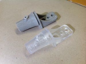
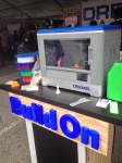
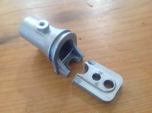
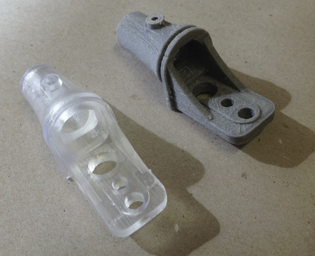
My first task was to print a replacement part for a plastic bracket used to mount a speaker which had snapped during use.

The broken speaker bracket (left) along with its slide on cover (right)

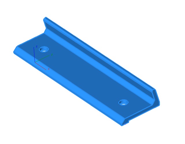
The first step was to replicate the part in a 3D modelling program. Using calipers and a ruler, I accurately measured and recreated the part in the parametric 3D modeller, Solidworks.

The speaker bracket modelled in CAD software.

It is worth noting that since I did not know precisely how the part was going to be used, I recreated all the features. Had I known which holes or bosses were not needed for example, I could have left them out of the 3D model.

The next step was to modify the part for improved strength. It was quite obvious where the part had failed and which area needed reinforcing. Nonetheless, I used a stress analysis tool on Solidworks to get a comprehensive look at stress occurring on the part when a load was applied.  I then increased the size of the arms and ran the stress analysis tool again. Part stress was significantly reduced. This version of the speaker bracket was to be printed and tested for use.

Stress analysis before and after.

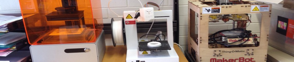
The part was printed on the Form1 printer which uses steroelithography technology which provides a much higher resolution than the cheaper extrusion printers. It’s estimated print time was 2 hours and 25 minutes while it’s total volume (including support material) was 15.7mL. So it is not exactly the fastest manufacturing method nor does it maintain 100% material usage efficiency since support material is discarded but this is more than made up for by the fact that there are ZERO tooling costs involved as well as negating the need to drive or travel anywhere to obtain the part, it can be created from the comfort of your own home.

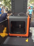
The Form1 3D printer


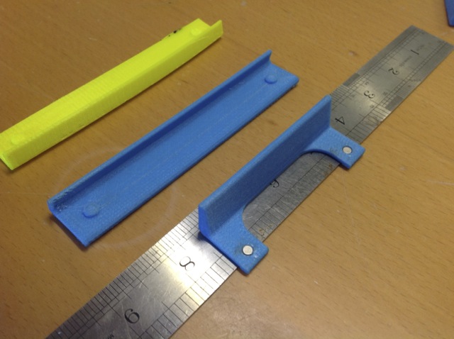
The part ready for print on Form1’s software ‘PreForm’ (left) and the actual printed part (right)

The part was printed at printer’s lowest and thus fastest resolution of 0.1mm (it ranges from 0.1mm – 0.025mm).  The print quality was stunning even on this setting and the tolerances were acceptable for such an application.

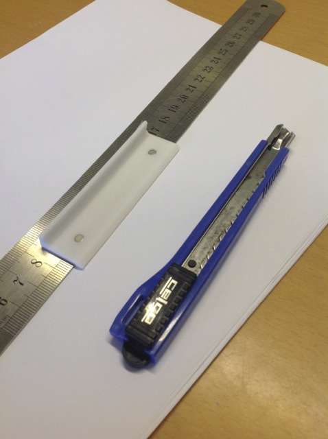
In an ideal world, prints could be used straight off the printer. Unfortunately though, that’s not the case. After coming off the machine, the print has to be soaked in a solution similar to methylates spirits for approximately 10 minutes and then the support material must be removed (roughly by hand at first then more precisely with the use of something such as the back edge of a stanley knife)

Peeling the support structure off the print.


The final part after removal of support material.

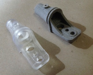
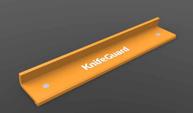
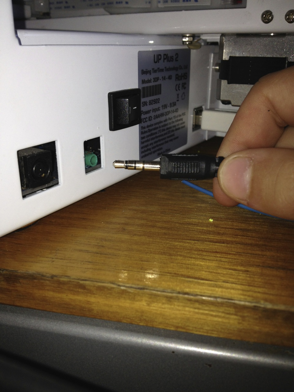
Success! The new printed part successfully fitted with the original plastic covering, including a fully functioning snap fit mechanism.

The original part alongside the new printed one.


Marcus Lee (UNSW)

IMG_1089 IMG_1004 IMG_1005

UP+ 2 and mac software challenges

The Up+ printer is a great little machine that prints robust models in ABS. But, the user experience could do with some refinement. The machine flashes and beeps like a cheap child’s toy, and has none of the theatre such as the subtle blue lighting of the MakerBot Replicator 2 or the sci-fi ‘R2D2’ voice of the Ultimaker servo motors. But these are minor gripes.

The biggest gripe is the Mac printer slicing software. The latest UP print software for Mac just refuses to load on the various Macs that I have access to. A workaround solution is to use software from Afinia – which does work on some macs. (Afinia is a rebranded UP+ for the North American market.)

One advantage of the latest print software is that it enables the printer to self-calibrate and level the bed. So with the software successfully loaded, the next challenge was to actually to get the machine to self-level ….. nothing happening! Fortunately, this is a common problem that can be solved by trimming a side of the sheath of the calibration cable mini-jack to remove interference, when plugged in, with the printers case. [see pic].  The value of a help forums and blogs are vital to keep these machine working!

Image


Working with Shapeways Update, Final Piece

After a fews weeks of waiting the final prints from Shapeways have arrived. Using three different printing technology illustrated bellow from left to right: FDM (Up Plus 2), SLA (Form 1) EBM – Electronic Beam Melting (Shapeways) I was able to conceptualise and finalise the design, each process offering different qualities. The FDM process producing excellent quality however needed support structures to form model, resulting in areas being filled in with irremovable supports. SLA process worked extremely well producing quality similar to FDM process with no support structures needed to form the piece, proving to be a better option in printing small intricate works. Finally, EBM – Electronic Beam Melting, whilst Shapeways employ numerous printing technology’s, I’m assuming to create the piece in ‘Polished Gold Steel ‘Enrobed in 24k gold’ this technology would have been employed due to the nature of the technology being able to print without support structures and in various metals; will have to follow up and check. The final piece came out better than expected without any printing problems, Shapeways proving to be an excellent printing service excelling in both quality and service.

Image

Image

Image